
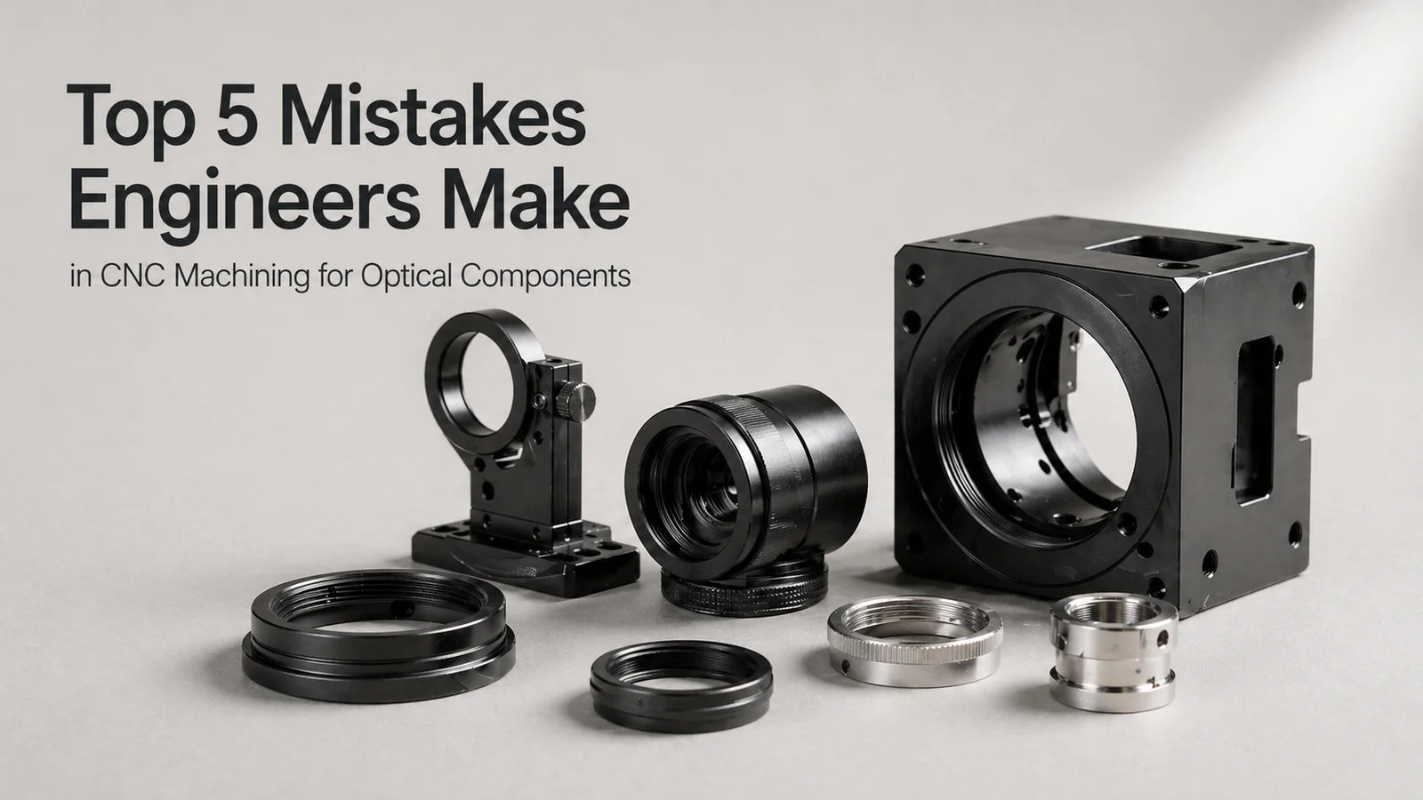

When designing optical components—lens barrels, LiDAR housings, sensor brackets, or imaging system assemblies—engineers often focus on the optical performance but overlook critical CNC machining details. Even a tiny error in tolerancing, material choice, or surface treatment can derail the entire project, causing delays, extra costs, or failed optical alignment.
At Joint Precision, we’ve supported hundreds of optical and photonics projects from prototype to production. Here are the top 5 most common mistakes we see engineers make—and how to avoid them.
1. Over-Tolerancing Every Feature
The Mistake
It’s common to mark all dimensions as tight tolerance (e.g., ±0.005mm) “just to be safe.” But when every single feature is held to the same extreme precision, you drastically increase machining time, scrap rates, and cost. Worse, it can force your manufacturer to use specialized setups or slower processes that add weeks to your lead time.
How to Avoid It
- Apply tight tolerances only where it matters: Focus on critical alignment bores, optical thread fits, and mating surfaces.
- Use GD&T to define true position, concentricity, and perpendicularity instead of generic linear tolerances.
- Work with your manufacturer early in DFM (Design for Manufacturing) to identify which features need high precision.
2. Ignoring Material Stability for Optical Applications
The Mistake
Choosing the wrong material (e.g., standard 6061 aluminum for high-precision optical assemblies) or ignoring thermal expansion coefficients leads to alignment drift, focus shift, or even component warping during operation.
How to Avoid It
- Match the material to your operating environment:
- 7075-T6 aluminum: Best for high-strength, lightweight optical housings
- Invar 4J36: Low thermal expansion for high-precision optical instruments
- TC4 titanium: Corrosion-resistant, stable for industrial and aerospace optics
- Discuss thermal cycling and operating temperature ranges with your CNC partner upfront.
3. Poor Surface Finish & Light Leakage
The Mistake
Optical components require controlled surface finishes to prevent stray light reflection and ensure consistent black anodizing adhesion. Engineers often specify generic “Ra 3.2μm” without considering the critical role of surface texture in light control.
How to Avoid It
- For light-tight applications, specify matte black hard anodizing with Ra ≤ 1.6μm on internal and reflective surfaces.
- Avoid sharp corners and deep grooves that trap machining residue and ruin coating uniformity.
- Ask your manufacturer about secondary processes like electroless nickel plating or black oxide for non-reflective, durable finishes.
4. Overlooking Assembly and Machinability
The Mistake
Designing features that are impossible to machine (e.g., deep internal threads with no tool access, thin walls <0.5mm) or impossible to assemble without damaging optical coatings. These force design changes late in the project.
How to Avoid It
- Use through-holes instead of blind holes where possible to allow full tool access.
- Keep wall thickness ≥1.0mm for most optical housings to prevent chatter during machining.
- Add assembly features (e.g., tool flats, alignment pins, and lead-in chamfers) early in the design phase.
5. Skipping DFM Review Before Prototype
The Mistake
Sending raw STEP files straight to machining without a Design for Manufacturing (DFM) review. Engineers often miss manufacturability issues until the first prototype fails, causing costly delays and redesign cycles.
How to Avoid It
- Always request a DFM review from your CNC partner before starting production.
- Share your full requirements: tolerance stack-ups, assembly sequence, environmental conditions, and optical alignment goals.
- Use the prototype phase to validate both the machining process and the optical performance, not just the fit.
Optical components demand precision—but precision without practical manufacturability is just a costly risk. By avoiding these 5 common mistakes, you can cut lead times, reduce costs, and ensure your designs move smoothly from prototype to production.
If you’re working on a new optical or precision component project, our engineering team can review your design and share actionable feedback.
👉 Contact us today to discuss your project and get a free DFM review.
